Monday 31 October 2011

GNU Chirp Sounder

This monday is yet another release from me. I'm publishing my code for ionospheric chirp sounding that I've been working on for a while. In lack of a better name, I'm calling it the GNU Chirp Sounder. It is a software defined radio based receiver for monitoring ionospheric sounders. The software is based on gnuradio and relies on Ettus research USRP2 and USRP N210 based digital receivers. The receiver can be used to receive the whole HF band (typically at 25 MHz bandwidth) simultaneously, and to receive multiple chirp sounders around the world simultaneously. The current receiver can be also used to perform single or dual polarization (channel) soundings. The dual channel mode can be used to determine the polarization form vertical soundings, or for angle of arrival measurements for horizontal soundings. It would also be trivial to add more channels for e.g., imaging or full polarization measurements.

The software consumes about 70% of one Intel Core i7 processor core, meaning that with a quad core processor, it is possible to simultaneously receive four different sounders, assuming that they are within the 25 MHz band that the receiver is tuned to.

What can I do with this? First of all, it is possible to use it to standard oblique ionospheric soundings, such as this one, between Sodankylä and Cyprus:
Oblique ionogram between Cyprus and Sodankylä. The Cyprus over the horizon radar installation transmits between 8 and 35 MHz with a 5 minute repetition period. This can be used to deduce ionospheric electron densities along the propagation path. 
Also, it is possible to perform standard vertical ionospheric sounding, such as this one:

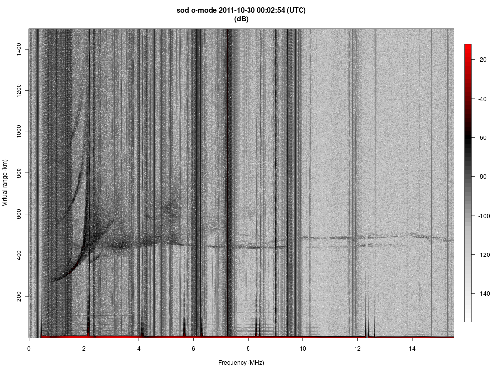
Vertical ionospheric sounding with the Sodankylä Ionosonde. The receiver is approximately 1 km from the transmitter. 
In the case of vertical soundings, it is possible use two antennas to determine the polarization of the vertical electromagnetic wave:
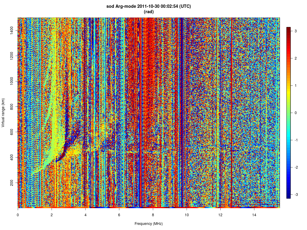
The phase difference between H and V polarizations. The greenish corresponds to O-mode of propagation and the blue corresponds to X-mode of propagation. 
As the receiver is relatively inexpensive and the hardware contains a GPS reference, it would be possible to perform 3D imaging of the ionosphere with this receiver, provided that there are enough of them.

Tuesday 11 October 2011

GNU Ionospheric Tomography Receiver (Jitter)

I am releasing the ionospheric tomography receiver that I have been
working on for a couple of years. The receiver is not related to the
GNU Digital Beacon Receiver provided by Prof. Mamoru Yamamoto, which
can be used for a similar purpose. The receiver looks at Russian
Tsykada, US Radcal, and DMPSF15 satellites that transmit 150 and 400
MHz beacon signals. The FORMOSAT satellites should also be usable,
although they do not seem to transmit anything above Northern
Scandinavia, so I haven't been able to test them. From these signals,
it is possible to derive the relative propagation delay between 150
and 400 MHz (other frequencies can also be used with the receiver).
The propagation delay is approximately related with the line integral
of the ionospheric electron density between the satellite and the
receiver. With a large enough network of receivers, it is possible to
perform limited angle tomography of the ionospheric electron density,
which is what my group is planning to do with this receiver.

The receiver package that I am now releasing is intended for use with
such a large scale tomography receiver chain. The receiver is capable
of autonomous operation and it can observe multiple beacon satellites
simultaneously. The receiver is written with C++ and the relative
propagation delay calculation is performed using GNU R. A normal PC
will be able to perform all of these calculations, although you will
need about 4 GB of memory for the phase curve calculation part.

I am not releasing any tomographic reconstruction software yet, but
this might happen in the future.

Here is the web site for my receiver, which I am choosing to call
Jitter (GNU Ionospheric Tomography Receiver):

http://www.sgo.fi/~j/jitter/web/

The software is still in alpha stage, but it has been used with
several test receivers for several months of continuous operation. I
have used it successfully with usrp1 and two WBX daughterboards, but
also recently I have managed to get USRPN210 and TVRX2 working. The
receiver can be locked to a GPS reference, but this is not necessary.
If you are interested using my receiver, feel free to contact me.

Thursday 6 October 2011

LOFAR Jülich DE605

Another international LOFAR station has been commissioned. Yesterday, 5th October 2011, the LOFAR station "DE605" was officially opened at Jülich in Germany. Their press statement read:

Bochum, Bremen, Jülich, 5 October 2011 – At last! The LOFAR station DE605 was officially opened on the campus of Forschungszentrum Jülich. The antenna station is an integral part of the digital radio telescope and European large-scale project LOFAR (Low Frequency Array). It will contribute to measuring long-wave radio signals from the dawn of the universe. LOFAR DE605 was built in cooperation between Ruhr University Bochum, Jacobs University Bremen and Forschungszentrum Jülich with funds provided by the Federal Ministry of Education and Research (BMBF).

This new station is one of five located in Germany. There are now eight operational international stations and, although there is still a lot of commissioning work to be done, it is great to see that the network has expanded so far so fast. The photograph below shows the newly completed station.

LOFAR station DE605. Image: Forschungszentrum Jülich

The opening of the facility is great news not just for the Bochum/Bremen/Jülich team, but also for the entire LOFAR facility. The addition of new baselines will improve the image quality and the additional collecting area will provide a valuable sensitivity improvement.

Congratulations to the German team on the completion of their new station!

Press-releases: