Thursday 31 March 2011

How do KAIRA and LOFAR work? — Part 7 : Phased arrays

Finally, we're onto the phased arrays!

The phased array concept is central to the LOFAR project. Phased arrays were developed by the German physicist Karl Ferdinand Braun in 1905. During the Second World War, they were used for radars, first by the Luftwaffe and then later by the US Air Force. After the war, they were introduced into radio astronomy, in particular by Sir Martin Ryle’s group at Cambridge. These days their use is quite common and they can be found in many radio applications.

Like a regular dish, they also rely on adding signals together. But the technique is different.

In a phased array, there is not just one detector, but several. Each can receive radio waves from all directions (well, if not all, then at least a very wide range of them).

Unlike the reflecting dish, which uses the physical travel of the incoming radio waves to get them to arrive in phase when they come from a certain direction, phased arrays don’t care when the signal gets to the detector.

They delay the electrical signal, instead.

The simplest way to do this is simply by adjusting the cable length. If you consider a two-element phased array, with identical cables, then you can see that a signal coming in from overhead will be detected at the same time, travel the same distance and thus add in phase, resulting in a strong signal.


At a certain angle away from directly overhead, the arrival times will vary by half a wavelength, so the electrical signals are completely out-of-phase when they add, and thus cancel each other out.


So this simple array is sensitive to signals coming from the zenith, but not to those coming from slightly off-zenith. In other words, this phased array has sensitivity in a particular direction.

Doesn’t seem particularly useful so far, but there’s a neat trick you can then do. And we’ll reveal what it is in the next episode!

Wednesday 30 March 2011

Is there aurora above Kilpisjärvi?

Several optical instruments measure continuously whenever the sky above northern Finland is dark. These instruments come in many versions with different purposes:

  • Meridian-scanning photometers scan the sky looking at one position at a time and measure one or more auroral emissions.
  • All-sky colour cameras have fisheye optics and nowadays image detectors with colour filter masks. Previously 16-mm or 35-mm cinematographic film was used. These cameras reproduce the aurora as it looks to the human eye.
  • Wide-band imagers are essentially sensitive black-and-white video cameras. They are useful for studying the structure (morphology) of the aurora, that is, to use the magnetosphere as a giant plasma physics lab.
  • Spectral imagers use narrow-band optical filters to measure the main auroral emissions quantitatively. From this the energy of the electrons impinging upon the atmosphere, causing the aurora, can be determined.

One of the Finnish MIRACLE all-sky camera stations is at Kilpisjärvi close to KAIRA. At the same station the University of Oulu deploys its optical instruments during the winter season. However, Kilpisjärvi is often overcast so look also at

Inverse Problems Africa 2012

Just in case you are wondering, you haven't accidentally stumbled into the wrong web log. However, although KAIRA is an Arctic project, we have some other collaborations and connections with other interesting project in other parts of the world. The following is posted on behalf of Lassi Roininen, from SGO.

The Inverse Problems Africa 2012 school and conference will be held in Bahir Dar, Ethiopia. These two back-to-back events will be held in October 2012. The events will cover both the theoretical and practical aspects of inverse problems in mathematics and physics with applications.

Featured topics include:
  1. Statistical inversion and incoherent scatter radar. Organiser: Markku Lehtinen, Finland, University of Oulu, Sodankylä Geophysical Observatory

  2. Epidemiology models and Markov chain Monte Carlo methods. Organiser: Heikki Haario, Finland, Lappeenranta University of Technology, Department of Mathematics and Physics

  3. Stochastic differential equations and their applications to pollutant dispersion in shallow waters. Organiser: Wilson Mahera, Tanzania, University of Dar es Salaam, Department of Mathematics

  4. Tomographic imaging. Organiser: Samuli Siltanen, Finland, University of Helsinki, Department of Mathematics and Statistics

Full details about the school and conference (including details about registration and travel) can be found at http://www.inverse-problems.org/

Tuesday 29 March 2011

Do meteors smoke?

Meteor smoke originates to the meteor ablation which takes place typically between 70 and 120 km. Estimates for the total meteoric input to the atmosphere vary from few tens to hundreds of tons per day.

After metal species are evaporated into atoms they start to interact with the atmospheric species forming metal oxides, hydroxides and carbonates which tend to coagulate by Brownian collisions into nm-scale particles called meteor smoke. Formation of the smoke takes place in timescales of a week, while the meteor smoke is redistributed by the global air circulation to maximize its concentration in the polar wintertime. In fact, due to sedimentation of the large meteor smoke particles, some fraction of the smoke will eventually enter to the ground level, especially in the polar regions and found from the ice-core drilling samples.


In general, the meteor smoke particles are of versatile scientific interest in the upper atmospheric research. As said, meteor smoke plays a key role in the chemistry of metallic species. Meteoric dust is thought to play a role in formation of noctilucent clouds and closely related anomalous polar mesospheric summer (and possibly winter) radar echoes (PMSE and PMWE). Charged meteor smoke particles, positive or negative, obviously contribute to the electron density budget of the D-region ionosphere which must be taken into account in the modelling. Despite of the scientific interest, relatively little is known about the meteor smoke properties. Even the fundamentals, like the actual chemical composition, size distribution, charging and finally what is the daily meteoric input to the atmosphere - all these are more or less open questions at the moment.

Charged meteor smoke can be detected in the incoherent backscattering as a narrow peak in the ion line. Novel radar techniques applied in the KAIRA will potentially provide a new insight to the meteors smoke and its role in the polar atmosphere.

Related links: http://www.sgo.fi/~j/kaira_ks.png

Monday 28 March 2011

How do KAIRA and LOFAR work? — Part 6 : Squinted vision

But what if the radio signal is not coming in from directly overhead? Well, as that signal goes away from the vertical position, the result will decrease. Not only will the reflected signals miss the receiver, but they will be adding out of phase as well.

At some angles, the radio waves from different parts of the system interfere. This can result in zero signal at certain angles where the radio waves from the different parts arrive out of phase, and enhanced signal at other angles where the radio waves arrive in phase.

So if you have a set of reflectors that are carefully adjusted to give good signal addition in a particular incoming direction, and then your radio signal moves, you have to tilt the entire set of reflectors and the receiver to follow it. That is, you change the direction in which your system is most sensitive. This is the reason why radio dishes are usually made so that they can be steered.

But this presents problems: as the size of the system gets bigger, you need more and more steel for the backing structure, bigger and bigger motors and better and better controllers to cope with structural deformations at different angles, wind loading and so on.

The elevation motors on the Kiruna 32m antenna.

An azimuth motor drive and gearbox
(grey+red) on the Kiruna 32m antenna.


As a result there is a limit as to how far you can go. Thus the largest fully-steerable dishes are typically 100 metres in diameter, such as the Effelsberg Radio Telescope in Germany.

The Effelsberg 100m radio telescope, Germany

This sort of size is about the limit at which structural and cost considerations make further enlargement prohibitive. Let’s face it, a large moving steel structure is complicated, difficult to maintain and very expensive to build. But there is an alternative...

(For those of you who are patient enough to have followed this so far, we’ve now covered all the pre-amble and can get on with the interesting phased array topic later this week!)

Photographs: Derek McKay-Bukowski

Sunday 27 March 2011

March snow assessment — Part 3

The last part of the snow assessment (23 March 2011), we'll look at just a couple of the many snow cross-sections taken. In the first photograph, we can see one of the depths of general snow cover.
It was measured next to northeast corner of the test antenna on the ground. The depth is approximately 80cm. The small lines on the rule are 1cm, and the large lines are every 5cm. A cross section was checked and Tero noted that there was first hard snow, grainy snow (darker areas), again hard, then grainy, hard and again grainy on the bottom. This is typical of the way that the snow is built up in layers during varying conditions of snow, wind and fair conditions.

In the next image, we can see the depth of snow on the top of one of the tiles.

Here is there 1-2cm of dense icy snow against the tile surface, with a second layer of 15-20cm of lightly packed snow over the top. Tero reported that there had been significant clearing of the snow due to the strong winds.


Photos: Tero Raita.

Saturday 26 March 2011

March snow assessment — Part 2

Following on from the last post, we'll now have a look at the raised tile. These photographs were taken on 23rd March 2011 during the special site inspection by Tero Raita.


The raised tile. Drift snow has reached part of the tile, but the high winds have kept the top of it moderately clear. In the background, is the Saana mountain.

Looking southwards. Originally, the warning markers had been partially covered. Here they've been cleared and reset. The snow bank is on the north edge of the frame, which is the direction from which the wind generally approaches.

Photos: Tero Raita

Friday 25 March 2011

March snow assessment — Part 1

On 23rd March 2011, a special site inspection was carried out to check on the snow conditions and to actually measure the snow before it starts to become subjected to Spring conditions. This was carried out by Tero Raita and we have the pleasure of posting up some of the great photographs that he took during that visit. We'll start with the ground-tile.


At this stage it remains difficult to make out the location of the tile, but it is more-or-less under the snow in the foreground of these photographs.


In the background of both images is the mountain Saana.

Photos: Tero Raita

How do KAIRA and LOFAR work? — Part 5 : The parabolic dish

As we saw in the last instalment, adding a reflector increases the received radio signal. And, we can continue to add more reflectors, each at the correct position and angle, to continue increasing the power of the combined radio wave.
If you do this enough, and imagine it in three dimensions, rather than two, you should understand the basic principle behind the traditional radio dish.


And, finally, for those trying to guess the faded dish photograph behind the last diagram here is view of the same structure, but from a slightly different angle.

This is the 25m dish at the Chilbolton Observatory in Hampshire, England. Next week, we’ll be considering directional sensitivity and starting to get down to the gritty detail of phased arrays!

Thursday 24 March 2011

KAIRA web log goes daily!

As the year ticks by, things are starting to get more and more busy. The summer build of the KAIRA project is looming, and there is a buzz of activity about the institute. And the seasons are changing too. At the equinox, there is some semblance of balance between the days and nights, and the long winter darkness seems behind us now. Of course, with the extra light and extra activities, there's going to be a lot more to report and a lot more photographs to share.

As a result, the KAIRA web log will be updated every day, including weekends! In fact, some days will see multiple posts.

So there will be a lot to see here over the next few months, both fun and factual.

We hope you enjoy it.

How do KAIRA and LOFAR work? — Part 4 : From radio waves to electrical signals

Now let’s imagine that we have a radio receiver that converts radio waves into electrical signals. If there is a certain strength of signal, then it generates a certain electrical output. To improve the sensitivity, we can amplify the electrical output. But that can only improve things so far. As the amplifier is turned up, it amplifies not only the signal, but also any noise in the system, which limits how much this can be done. So instead, we need to somehow increase the power of the incoming radio signal.

One way to do this is to collect more signal in the first place. Let’s say we have a radio receiver, which is picking up signals from space. To get more of that signal into the radio receiver, we could take a reflector (say a sheet of metal) and bounce some signal onto the receiver. Then, we could add a second reflector and bounce in some more signal; effectively doubling the amount of radio waves that are received.


(Don't forget you can click on images and diagrams to see enlarged versions!)

This is fine, but in order for this to work well, the signals should optimally be added in phase. Because Reflector 1 is closer to the receiver than Reflector 2, the waves it is reflecting arrive at the receiver first. Because the two signals do not arrive together, they are out of phase and reduce the final result.

To get them to add “in phase”, we must somehow delay the signal from Reflector 1. The easy way to do this is to put the reflector a bit further back. That way it takes longer to get the reflector in the first place, to compensate for the fact that it has less to travel from the reflector to the receiver.


If we label the radio signal paths for a single wavefront as a, b, c and d, then for the waves to add in phase the combined length a+b must be the same as c+d. (Yes, I know, this is starting to look dangerously like equations, which I promised to avoid!)


To be continued...

Wednesday 23 March 2011

How do KAIRA and LOFAR work? — Part 3 : Start with the radio waves

Phased receiver arrays like KAIRA and LOFAR work by exploiting the physical effects of constructive and destructive interference. Before we consider how they do this, we need to go back a step and consider how radio observations are made. So to start, let’s think about a radio signal, which is represented as a wave. If you have two of these signals at the same frequency (or wavelength), you can add them together. If they are lined up, then they will add together and get stronger. However, if they are not quite lined up, then they don’t always add with each other, so the result is weaker. In fact, there is an alignment where they are doing the exact opposite of each other and thus cancel each other out.


(Don't forget your can click on the images to see enlarged versions!)

This alignment of two waves (or a single wave to a reference point) is called its phase. When waves line up they are said to be “in phase” and when they are exactly mis-aligned they are said to be “out of phase”. So let’s now think about how this principle applies to a signal coming from a distant astronomical source.

Two of the challenges of astronomy are that the incoming signals from space are very weak and that in order to “see” the object under study, the observation needs to be able to make out fine detail. In other words, the telescope needs to have high sensitivity and high resolution.

Because astronomical objects are so far away, the transmitted radio waves from a star or galaxy are effectively planar when they reach us — that is, the incoming wavefront is flat and – to all intents and purposes – the signal appears to be coming from the same absolute direction no matter where you are.

As the illustration shows, the further away from the source you get, the flatter the wavefront seems. And that's over a very small distance on a computer screen. Imagine if it was coming from a radio-source deep in space.

And in the next instalment, we’ll look at how we can use the in-phase and out-of-phase properties of the radio signals.

Tuesday 22 March 2011

EGU web logs

Hey, just because we're running a long series on how phased arrays work, doesn't mean that we'll be 'news-free' during this time. In fact, we intend to post even more regularly, with material on weekends and overnight. And we'll be coving some significant scientific community events too!

For example, we're now listed on the EGU 2011 web log roll. During the EGU General Assembly, we'll be posting regularly with updates and information about this significant conference.

Okay... end of announcement. Stay tuned for more news (and the next instalment of our article series!)

How do KAIRA and LOFAR work? — Part 2 : What is a LOFAR system?

Before we get started on the explanation, let’s take a moment to quickly describe ASTRON's LOFAR project on which KAIRA is based. The LOFAR (LOw Frequency ARray) radio telescope is a distributed system; namely, it is not all located at a single site. Instead, it is split into dozens of separate locations called “stations”. Most of these stations are in the north of the Netherlands, but there are also a few scattered further afield in Germany, France, Sweden and the United Kingdom. (KAIRA is effectively a single LOFAR station, but with some interesting features and a few special extras.)

Typically, each station has two fields containing arrays of antennas. These are referred to as the Low-Band Array (LBA) and High-Band Array (HBA). The “low” and “high” refer to the radio frequencies that these arrays are designed to receive. The LBA is optimised for the frequency range 30–80 MHz and the HBA for 120–240 MHz. The gap between the two bands is where FM radio is broadcast. It is pointless trying to listen to faint radio signals from the depths of space, when these powerful radio transmitters are nearby. Thus, LOFAR ignores this part of the radio spectrum. And, rather than designing one type of array which straddles this gap, it has been split into the two arrays, with the LBA and HBA being specifically tuned to the respective parts of the radio spectrum.

Aerials of a LOFAR Low Band Array.


Tile antennas of a LOFAR High-Band Array


Apart from the different antenna designs, the arrays are also arranged slightly differently. The LBA is made up of a scattering of spindly aerials that look like wire pyramids. The HBA comprises large flat black-plastic tiles packed sided by side. There are some good reasons for these differences, but ultimately each of them is a phased array receiving radio waves from space.

And we’ll continue with that tomorrow!

Photos: Derek McKay-Bukowski, STFC

Monday 21 March 2011

How do KAIRA and LOFAR work? — Part 1 : Introduction

KAIRA (Kilpisjärvi Atmospheric Imaging Receiver Array) is a radio receiver system. It can measure very faint radio signals and determine very precisely which directions those signals are coming from. It uses LOFAR antennas and signal processing to accomplish this. If you ignore the details of how the data are processed and interpreted, you can safely say that antennas of LOFAR and KAIRA are doing the same sort of thing.

LOFAR (LOw Frequency ARray) is a radio telescope, designed by the Netherlands Institute for Radio Astronomy — ASTRON. Unlike the so-called traditional radio telescopes, which use large parabolic dishes, LOFAR has fields of antennas, which do not move. Instead, it uses electronics and computing to change which way the telescope is looking in the sky. With no moving parts, one is often asked how it works. The problem is that the answers often come in two extremes.

The first is that there is some glib statement that simply reiterates how the 'signals from all the antennas are combined to emulate a large telescope and that the telescope uses digital technology to change the direction that it points in the sky'.

The second is a full-blown lecture course that starts 'Consider electromagnetic radiation from direction s from a small elemental solid angle dΩ, at frequency υ, within a frequency width dυ'. From there it quickly degenerates into page after page of equations.

For the next few weeks we’ll be posting a series of articles to the KAIRA web log in addition to our regular photographs and reports. These articles will steer the middle ground between the two extremes. Of course the entire topic can be extremely complex, and there are many complications and assumptions that we’ll have to skip over to avoid getting bogged down in the detail. (For the experts out there, please indulge us these simplifications.) And yet, we intend to go into sufficient detail, step-by-step and without mathematics, to explain with words and illustrations how KAIRA and LOFAR will accomplish their amazing observations.

Friday 18 March 2011

EISCAT Svalbard Radar — Part 3

There was one last photograph to share while we're on the topic of the EISCAT Svalbard Radar (ESR). I had intended to post it at the end of yesterday's web-log entry, but it was such a beautiful photograph that I decided to save it for a Friday. (This Friday-Photo is starting to become a regular feature!) So, although yesterday's post was a bit short, hopefully this will make up for it.

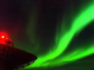
The photograph is of the ESR 42m dish during polar night. The stunning green of the Aurora Borealis (northern lights) is clearly visible. The bright red glow is the aircraft warning light on the top of the dish. And, if you look carefully, you can make out some of the stars in the inky-black Arctic sky. The photograph was taken by Alan Wood from University of Aberystwyth during a radar campaign in January 2006.

ESR 42m and aurora. (Photo: Alan Wood)

Have a nice weekend.

Thursday 17 March 2011

EISCAT Svalbard Radar — Part 2

The ESR transmitter is modular in design, using 16 small klystrons based on TV transmitter technology. The transmitter has a central operating frequency of 500 MHz. At the time of writing this article, the two dishes cannot be used exactly simultaneously. However it is possible to alternate between the dishes on a timescale of approximately 5 seconds. Two receiver systems are available which (for instance) allow ion line and plasma line data to be recorded simultaneously.

The transmitter hall of the ESR. (Photo: Derek McKay-Bukowski)

Wednesday 16 March 2011

EISCAT Svalbard Radar — Part 1

If you have looked at the EISCAT map, you will see that we have covered the three mainland sites: Tromsø, Kiruna and Sodankylä. But what of the one to the north?

Yes, EISCAT actually runs a fourth station on the Norwegian-administered archipelago of Svalbard. This is the the EISCAT Svalbard Radar (ESR), located near the settlement of Longyearbyen.

Longyearbyen at midday in late January
2006.
(Photo: Derek McKay-Bukowski)

The ESR system comprises two dishes. One is a fully-steerable 32m dish, which is similar in design to the mainland system. The other is a 42m fixed dish, which is 'field-aligned'. The 'field' in question is the Earth's magnetic field; which arcs out of the magnetic poles. The direction at which the 42m dish is pointing is precisely the same angle at which the magnetic field leaves the Earth's surface.

The two dishes on Svalbard. The fixed 42m is
on the left and the steerable 32m dish is on
the right (Photo: Tony van Eyken, EISCAT)


The 32m dish was built in 1994 and the first observations were taken in 1996. The 42m dish was added in 1999 with observations starting in 2000. The transmitter output can be routed to either antenna as required.

The 32m dish is fully steerable. Despite the 275 ton weight, it can scan at 80 degrees per minute both in azimuth and in elevation and is capable of acceleration from 0 - 100% in 2 seconds.

Tuesday 15 March 2011

A visit to ASTRON

There was a one-day visit to the ASTRON headquarters today. ASTRON is the Netherlands Institute for Radio Astronomy, and one of the world's leaders in this field.

Located in the north of the Netherlands, near the village of Dwingeloo, this establishment has a long history in radio astronomy, including the Dwingeloo Radio Telescope. This 25m radio dish was completed in 1956 and, at the time, was the largest radio telescope in the world. Although this venerable instrument is still operational, ASTRON is more widely known these days for building, operating and leading the LOFAR project. However, there are lots of other areas that ASTRON works on, including the Westerbork Radio Telescope array, which is located nearby, and participation in the Square Kilometre Array.

ASTRON operates under the umbrella of the Dutch national research council, NWO (Nederlandse Organisatie voor Wetenschappelijk Onderzoek). Also located on the same site, is the Joint Institute for VLBI in Europe (JIVE). This affiliated organisation is responsible for Very Long Baseline Interferometry (VLBI) and has its headquarters and data processing facility located here.

The visit today was very successful and a lot of interesting topics were covered... not just KAIRA, but also LOFAR, EISCAT and SKA work. One thing of particular interest, is the production methods that ASTRON are developing for the AA-mid (mid-range frequency aperture arrays) part of the SKA project. These VHF antennas systems could be of particular use to the ESICAT_3D project as a way of generating huge phased array systems.

Photo: Derek McKay-Bukowski

Monday 14 March 2011

EGU 2011 General Assembly

KAIRA will be making two presentations at the EGU General Assembly 2011. This massive conference brings together geoscientists from all over the world into one meeting covering all disciplines of the Earth, Planetary and Space Sciences.

The first presentation will cover the KAIRA project itself, outlining what it is, the status of the project, and the amazing things planned for 2011. The second presentation, entitled "Lateral Thinking - Sharing Technology Across Disciplines" will look at how KAIRA links other research projects, such as EISCAT, SKA and LOFAR and how all scientific endeavours can take practical steps to boost their own experiments and facilities.

EGU (European Geosciences Union) is non-profit association open to individuals engaged in geoscience and various other related disciplines. Here are some related EGU links:

EGU homepage: http://www.egu.eu/

EGU GA 2011 web log: http://egu2011.wordpress.com/

EGU GA 2011 twitter: http://twitter.com/egu2011

Friday 11 March 2011

Arctic twilight

Last Friday, I finished the week's web-logging with just a nice photograph. Since then, I've received loads of e-mails (where 'loads' = 2) saying that it was a great idea. So, let's try the experiment again!

This week's 'end-of-week' image is also from the EISCAT receiver station at Kiruna. Like the other photograph, I took this while I was living there in 2006. Although cloud often masks out the beautiful aurorae, sometimes having some clouds is not such a bad thing. And radio-dishes always make for wonderful silhouettes.

Have a nice weekend!

Kiruna 32m at dusk. (Photo: D. McKay-Bukowski)

Thursday 10 March 2011

The EISCAT UHF transmitter

If you read the previous web log post about the EISCAT site at Sodankylä, you may be wondering how a dish fitted with a UHF receiver can receive signals from a VHF transmitter at Tromsø. Well, that's because there is actually a second transmitter at the Tromsø site.

As we mentioned in the first post about the EISCAT facilities near Tromsø (Norway), there is a radar there which operates at 931 MHz. Like the receiver dishes in Kiruna and Sodankylä, the UHF transmitter system in Tromsø is also a 32-metre diameter dish, although of a slightly modified design. This is because of the additional waveguides required by the transmitter, which take the high-power signals from the klystrons in the so-called transmitter hall, out to the dish and then through a couple of rotating wave-guide joints to get it to the focal position for beaming into the upper-atmosphere.

Together with the passive receivers at Kiruna in Sweden and Sodankylä in Finland, EISCAT’s Tromsø UHF radar transmitter forms this tri-static system. The UHF system has been operating since 1981, with several major upgrades in the intervening period.

Wednesday 9 March 2011

EISCAT-Sodankylä

If you have looked at the map showing the positions of LOFAR, EISCAT and KAIRA, it will be apparent that there is actually three EISCAT sites on the Fenno-Scandinavian mainland. Apart from the transmitter site at Tromsø and the receiver site at Kiruna (home of the EISCAT_3D demonstrator array) there is also an EISCAT site in Finland.

This is actually located at Sodankylä Geophysical Observatory, the institute behind the KAIRA project. Like the Kiruna site, the EISCAT system in Sodankylä is a receiving station (there is no transmitter). The two dishes are copies of each other, built at the same time and deployed to the two sites. They are fully-steerable, 32m-diameter, prime-focus paraboloids. Both are fitted with UHF receivers (although on occasion other receiving systems have been fitted for specific experiements). The photograph shows well the backing structure and counterweights of the Sodankylä dish.

In fact, at the time these were built, there were two other identical dishes built, which were deployed as part of the European VLBI Network in Italy (one at Medicina and one at Noto).

Apart from some of its own unique research projects, the 32m dish at Sodankylä acts as a one of the receivers for bi- or tri-static ionospheric radar observations.

Photo credit: Th. Ulich

Tuesday 8 March 2011

Testing SETI with LOFAR

The KAIRA team has learned that LOFAR test observations have coincided with the 3rd observing run of Project Dorothy. The LOFAR station used was the British LOFAR station (UK608), located at Chilbolton, Hampshire. The Project Dorothy observing run was carried out on the early (Euro-) mornings of the 3rd and 4th of March 2011, with the targets being the so-called Kepler planets, identified by the Kepler mission and other related projects. The aim of Project Dorothy is to provide observations on more than 85 of these candidate sources (including KOI 268.01 and KOI 701.03).

For the LOFAR participation, the work carried out was principally for evaluation of the software systems. The latest tests involved pointing at three different places in the sky at once (using the multi-beam capacity), and also testing if data could be taken at 1 Hz frequency resolution across a full band 36 MHz wide. If these tests are successful, it will pave the way for further use of the LOFAR system for SETI observations.

Station UK608 is still being commissioned in certain areas and the opportunity to carry out this work was fortuitous. The LOFAR-UK observations were organised at the last moment to provide additional coverage of these joint US-Japan observations. Although highly experimental, it appears that data has been successfully taken by the radio telescope, which is great news for LOFAR, and a tribute to the team from SEPnet/Oxford University who provided data acquisition system and managed to get the observations scheduled at the last minute.

Additional programmes are planned for the same observing window approximately 24 hours later with the possibility of further follow-up observations.

What this demonstrates is the flexibility of modern digital radio-telescopes like LOFAR, KAIRA, etc. to react to interesting and challenging observing opportunities.

Thanks to LOFAR-UK and Project Dorothy for the above information.

Monday 7 March 2011

Early-March status

Wow! The year is moving on and the first site image for March has now come in. The photograph featured in this web log post was taken by a member of the KAIRA team on 4th March 2011. The raised tile is clearly visible on the right, but the ground tile still remains blanketed by snow. It is just possible to make out its position on the left of the photograph behind one of the posts.


We are now entering an interesting time. Temperatures are starting to rise, sometimes even hitting highs of –10 degrees celsius. From a technical point of view, this is a challenging period for the test antennas, as they will be subjected to ever-compacting snow. There is also the chance of localised melting and re-freezing, especially in the places where direct sunlight can strike the black antenna covers and warm them up. These are the sorts of conditions where ice movement can cause significant damage. Only a few months to go and we'll know if this experiment has worked.

But is will also be interesting from a more artistic sense. As the Arctic approaches the equinox, there is, for a few weeks, a semblance of normal day and night. This is accompanied with a great variety of lighting directions and conditions, plenty of sunshine and some still inky-black nights. Being the tail end of winter, the weather is much nicer, with more snow on the ground and less cloud in the sky.

No doubt, there will be some more lovely photographs to come.

Photo credit: Markku Postila

Friday 4 March 2011

Kiruna dusk

'I once lived in a place ...'

While going through the photographs for the previous weblog entry, I stumbled across this one. It was taken during the late summer at the Kiruna receiver station, which is part of the EISCAT radar er receiver network. At the time, this was also where I was living (I have a tendency to live at observatories). At this time of the day and year, the lights and colours of the sky can be breathtaking. So, as a nice way to finish the week, let's just end with a photograph.

Enjoy.

Thursday 3 March 2011

Crossing borders

KAIRA will be built at Kilpisjärvi (hence the name!). If you have had a look at the map where this is, you will see it is not far from the international border between Norway and Finland.

Ignoring the border guards and customs station for the time being, the crossing into Norway is marked simply and to the point. 'Norge' (which is Norwegian for Norway, of course). The long road then heads on to the distant towns of Skibotn and Lyngen.

Going the other way, you are entering Finland (written in Finnish, English and Sami language) and, of course, this is shown in the livery of the European Union. After all, this is border not just with Finland, but with the entire of the EU.

The settlement of Kilpisjärvi itself is not far from the border, so there is not far to go once you've entered Finland.

However, not far away from the crossing point is the original border marker.

It is nice to see this old border marker from a bygone era.

(Note: I took these photographs at the height of summer 2006. Of course at the time I'm posting this weblog entry, these vistas are completely white.)

Wednesday 2 March 2011

Space debris

Space debris is an ever growing environmental problem occurring in space. After over 50 years of space rocket launches, our near space is littered with approximately 10^6 objects larger than 1 cm in diameter, weighing a total of 5500 tons (Nasa ODQN Jan 2010). As the atmosphere is very thin in near-Earth space, these objects do not come down very quickly, causing danger to Earth orbiting spacecraft for tens or hundreds of years to come. Once these objects are in space, there is also a probability that these objects will eventually collide with each other and create even more debris. As the probability of in flight collisions increases as a function of debris in orbit, a catastrophic collisional cascade process that renders regions of near-Earth space unusable is a real risk. This scenario is often referred to as the Kessler syndrome. A video of the evolution of space objects is shown below.


A hypervelocity collision.


EISCAT has been active in space debris measurements for over 10 years, producing hundreds of hours of space debris measurements, covering two major break ups: the Chinese anti-satellite collision and the collision of the Iridium and Cosmos satellites.

Most of the measurements are so called beam-park measurements where the antenna is positioned at a fixed pointing. During a 24-hour period, while the Earth rotates around its axis, a representative statistical sample of debris is measured, containing information on orbital elements of the debris. The time of day provides information on the longitude of the ascending node, while the Doppler shift gives information on the inclination of the object. An example measurement produced after the collision of the Iridium and Cosmos satellites is shown in the figure below.

EISCAT UHF beam park measurement of the Iridium-Cosmos collision
debris clouds. Each point represents a detection of an object passing
the radar beam, the color represents radial Doppler shift. full sized version.

One of the potential uses of the planned EISCAT3D system is to track space objects and space debris. One of the advantages of a phased array system is the capability of observing a large volume of space simultaneously and making interferometric direction angle measurements. This will allow accurate trajectory measurements that can be used for collision avoidance with operational spacecraft, such as the International Space Station or Envisat.

For more information on EISCAT space debris activities can be obtained here.

Tuesday 1 March 2011

SKA — Square Kilometer Array (Part 2)

This article follows on from yesterday's discussion of the Square Kilometre Array (SKA) project.

The SKA will operate over a wide range of frequencies (70 MHZ to 10 GHz) and, like KAIRA, it will be split into different antenna arrays to cover these different frequency bands. The reason for this is that there is no single antenna design that can cover the entire frequency range efficiently.

As a result, the SKA will comprise arrays of three types of antenna elements. These arrays are referred to as the SKA-low, SKA-mid and SKA-dish arrays.


The SKA-low array uses simple dipole antennas to cover the frequency range from 70 - 200 MHz. These will be grouped in 100m diameter stations each containing about 90 elements. This system is very similar to the existing LOFAR Low-Band Array layout.

An artist's impression of the SKA-low dipoles. (Image:
SPDO/Swinburne Astronomy Productions)


The SKA-mid array is again LOFAR-like. It will most likely comprise more delicate antennas, assembled into 'tiles', which are then configured into arrays. These tiles cover the medium frequency range from 200 to 500 MHz, with tiles clustered together into circular stations.

An artist's impression of the SKA-mid tile cluster.
(Image:
SPDO/Swinburne Astronomy Productions)


The SKA-dish array will have several thousand antennas in the more traditional 'dish' form to cover the frequency range 500 MHz to 10 GHz. The plan is to equip these dishes with focal plane arrays at their focus to increase their field-of-view (a limitation of traditional dishes).

An artist's impression of the SKA high-frequency dishes.
(Image: SPDO/Swinburne Astronomy Productions)

There are lots of links on the Internet about the SKA project. However, the official project web site is: http://www.skatelescope.org/