 |
| The KAIRA site (Photo: D. McKay-Bukowski) |

Showing posts with label HBA. Show all posts
Showing posts with label HBA. Show all posts
Friday, 29 August 2014
Typical KAIRA
Today's photo has a bit of everything. The LOFAR HBA tiles, the LBA array in the background, Saana dominating the horizon, the storage containers and site area, and our trusty observatory vehicle.

Sunday, 24 August 2014
Missing in action
Today's photograph shows the frameset of HBA tile #75. Or, we should say... the former HBA tile #75. It is missing due to a severe blizzard that swept through the site at the beginning of the year. We are still waiting for a quote from ASTRON to get this replaced.
 |
| Frameset for HBA tile #75 (D. McKay-Bukowski) |
Monday, 11 August 2014
Moody KAIRA
Arrived at KAIRA pretty late last night. It was a moody scene. Low cloud lurking over Pikku Malla and everywhere damp and foggy.
 |
| Low cloud over KAIRA (Photo: D. McKay-Bukowski) |
Friday, 1 August 2014
KAIRA Pan-Lapse Film

Right on the first evening, we put a tripod bridging the gap between tiles H57 and H47 on which we mounted a wide-angle GoPro camera, which was glued onto a very cheap and simple egg timer. The egg timer rotates 360° in one hour, and the camera was set to take a photo every 10 seconds, thus taking 360 images, one per degree of rotation.
The full 360° panorama can be assembled by sticking together twelve images, which are five minutes apart. The only problem is to find out how many pixel the image rotates in five minutes, which is 30° of rotation.
The photo above shows such a montage (click to enlarge), featuring the famous mountain of Saana in the sixth pane from the left. Since we have a full rotation, one photo per degree, we can assemble such a panoramic view in 360 different directions, each one showing the a full 360° panorama. Then, we combined them into a short film, giving the impression of full-panorama rotation.
The above explains how we did it, but one can understand what's going on also this way. We generate a time-lapse film from all the images, showing a slow rotation. Then we cut out the centre vertical section equivalent of 30° rotation from this film. Thereafter we glue twelve copies of the very same film side-by-side, but advance the film for each step just the right amount, so that it fits to the previous copy of the film.
We hope you enjoy the result.
We got the idea for these pan-lapse films from Ken Murphy of Murphlab, please visit his site for this and other exciting time-lapse projects.
Photos & pan-lapse: Thomas Ulich.
PS1: You might wonder why we didn't choose a nicer day with more blue sky for this experiment. In fact we did, but due to the GoPro's automatic exposure settings, the large contrasts between looking into the Sun and away from the Sun, paired with shadows of clouds moving across the sky, make the different panes/frames look very different and the result is much less pleasing. So grey skies are good for something!
PS2: Another somewhat more explicit blog post about this went out today on the MiVyoo blog.
Saturday, 5 July 2014
Piglet-tail hooks
During the blizzard in March, some of the screws that held the HBA anchors were bent out of shape, resulting in the anchor coming loose. In other cases, the S-haakje would deform to release the anchor.
We have been experimenting with alternative anchor designs to try and come up with a more secure way to hold the anchors in place. Although we cannot change the staafje, we can replace the way the O-ring connects to the timber frameset.
One method is to use a spiralled hook which we refer to as a 'piglet-tail hook'. This lets the O-ring be connected without it requiring the drill. On the other hand, the extra loop still prevents the O-ring from coming loose in the event of extreme wind buffetting.
We have been experimenting with alternative anchor designs to try and come up with a more secure way to hold the anchors in place. Although we cannot change the staafje, we can replace the way the O-ring connects to the timber frameset.
One method is to use a spiralled hook which we refer to as a 'piglet-tail hook'. This lets the O-ring be connected without it requiring the drill. On the other hand, the extra loop still prevents the O-ring from coming loose in the event of extreme wind buffetting.
 |
| 'piglet-tail' hooks on tile H76. (Photo: D. McKay-Bukowski) |
Thursday, 3 July 2014
HBA billowing
In high winds, the covers of the HBA tiles can billow up. This places stress on the edges of the covers and, in extreme conditions, can lead to tile failure. During the recent repair work we had several occasions where this billowing effect was visible.
 |
| HBA tiles billowing up along the NW edge (Photo: D. McKay-Bukowski) |
Tuesday, 1 July 2014
Fixing HBA damage
In March we lost one HBA tile and had several others damaged by the blizzard. Last week we repaired one of the more badly damaged tiles, replacing shattered polystyrene parts and re-securing the cover.
 |
| Assessing H65 (Photo: D. McKay-Bukowski) |
 |
| Internal damage on HBA H65 (Photo: D. McKay-Bukowski) |
Sunday, 15 June 2014
KAIRA EISCAT VHF intersection heights/elevations
In order for the KAIRA beam to intersect the vertical EISCAT VHF transmitter beam, the elevation must be set as follows. (All data provided by I.I.Virtanen, U. Oulu).


Note that the azimuth to the EISCAT VHF is 313.95 degrees. The numbers for the above plots are as follows. Hgt is the height above the EISCAT VHF transmitter in kilometres and Elev is the require elevation of observation from KAIRA to have the beam centre at this height.
We hope you read all these numbers and memorised them!
Note that the azimuth to the EISCAT VHF is 313.95 degrees. The numbers for the above plots are as follows. Hgt is the height above the EISCAT VHF transmitter in kilometres and Elev is the require elevation of observation from KAIRA to have the beam centre at this height.
| Hgt | Elev | Hgt | Elev | Hgt | Elev |
| 0 | -0.735 | 670 | 82.155 | 1340 | 85.69 |
| 10 | 6.101 | 680 | 82.259 | 1350 | 85.717 |
| 20 | 12.747 | 690 | 82.359 | 1360 | 85.743 |
| 30 | 19.044 | 700 | 82.457 | 1370 | 85.768 |
| 40 | 24.881 | 710 | 82.552 | 1380 | 85.793 |
| 50 | 30.199 | 720 | 82.644 | 1390 | 85.818 |
| 60 | 34.987 | 730 | 82.734 | 1400 | 85.843 |
| 70 | 39.261 | 740 | 82.821 | 1410 | 85.867 |
| 80 | 43.06 | 750 | 82.906 | 1420 | 85.891 |
| 90 | 46.431 | 760 | 82.989 | 1430 | 85.914 |
| 100 | 49.423 | 770 | 83.07 | 1440 | 85.937 |
| 110 | 52.082 | 780 | 83.148 | 1450 | 85.96 |
| 120 | 54.451 | 790 | 83.225 | 1460 | 85.982 |
| 130 | 56.568 | 800 | 83.3 | 1470 | 86.005 |
| 140 | 58.467 | 810 | 83.373 | 1480 | 86.027 |
| 150 | 60.176 | 820 | 83.444 | 1490 | 86.048 |
| 160 | 61.719 | 830 | 83.513 | 1500 | 86.069 |
| 170 | 63.117 | 840 | 83.581 | 1510 | 86.09 |
| 180 | 64.39 | 850 | 83.648 | 1520 | 86.111 |
| 190 | 65.551 | 860 | 83.712 | 1530 | 86.132 |
| 200 | 66.613 | 870 | 83.776 | 1540 | 86.152 |
| 210 | 67.589 | 880 | 83.837 | 1550 | 86.172 |
| 220 | 68.488 | 890 | 83.898 | 1560 | 86.192 |
| 230 | 69.318 | 900 | 83.957 | 1570 | 86.211 |
| 240 | 70.087 | 910 | 84.015 | 1580 | 86.23 |
| 250 | 70.801 | 920 | 84.072 | 1590 | 86.249 |
| 260 | 71.465 | 930 | 84.127 | 1600 | 86.268 |
| 270 | 72.084 | 940 | 84.181 | 1610 | 86.287 |
| 280 | 72.663 | 950 | 84.234 | 1620 | 86.305 |
| 290 | 73.205 | 960 | 84.286 | 1630 | 86.323 |
| 300 | 73.714 | 970 | 84.337 | 1640 | 86.341 |
| 310 | 74.192 | 980 | 84.387 | 1650 | 86.358 |
| 320 | 74.642 | 990 | 84.436 | 1660 | 86.376 |
| 330 | 75.067 | 1000 | 84.484 | 1670 | 86.393 |
| 340 | 75.468 | 1010 | 84.531 | 1680 | 86.41 |
| 350 | 75.847 | 1020 | 84.577 | 1690 | 86.427 |
| 360 | 76.207 | 1030 | 84.622 | 1700 | 86.443 |
| 370 | 76.548 | 1040 | 84.667 | 1710 | 86.46 |
| 380 | 76.872 | 1050 | 84.71 | 1720 | 86.476 |
| 390 | 77.18 | 1060 | 84.753 | 1730 | 86.492 |
| 400 | 77.473 | 1070 | 84.795 | 1740 | 86.508 |
| 410 | 77.752 | 1080 | 84.836 | 1750 | 86.523 |
| 420 | 78.019 | 1090 | 84.876 | 1760 | 86.539 |
| 430 | 78.274 | 1100 | 84.916 | 1770 | 86.554 |
| 440 | 78.518 | 1110 | 84.955 | 1780 | 86.569 |
| 450 | 78.751 | 1120 | 84.993 | 1790 | 86.584 |
| 460 | 78.974 | 1130 | 85.031 | 1800 | 86.599 |
| 470 | 79.188 | 1140 | 85.067 | 1810 | 86.614 |
| 480 | 79.394 | 1150 | 85.104 | 1820 | 86.628 |
| 490 | 79.591 | 1160 | 85.139 | 1830 | 86.643 |
| 500 | 79.781 | 1170 | 85.174 | 1840 | 86.657 |
| 510 | 79.963 | 1180 | 85.209 | 1850 | 86.671 |
| 520 | 80.139 | 1190 | 85.243 | 1860 | 86.685 |
| 530 | 80.308 | 1200 | 85.276 | 1870 | 86.698 |
| 540 | 80.471 | 1210 | 85.309 | 1880 | 86.712 |
| 550 | 80.628 | 1220 | 85.341 | 1890 | 86.725 |
| 560 | 80.78 | 1230 | 85.373 | 1900 | 86.739 |
| 570 | 80.927 | 1240 | 85.404 | 1910 | 86.752 |
| 580 | 81.068 | 1250 | 85.435 | 1920 | 86.765 |
| 590 | 81.205 | 1260 | 85.465 | 1930 | 86.778 |
| 600 | 81.337 | 1270 | 85.495 | 1940 | 86.79 |
| 610 | 81.466 | 1280 | 85.524 | 1950 | 86.803 |
| 620 | 81.59 | 1290 | 85.553 | 1960 | 86.815 |
| 630 | 81.71 | 1300 | 85.581 | 1970 | 86.828 |
| 640 | 81.826 | 1310 | 85.609 | 1980 | 86.84 |
| 650 | 81.939 | 1320 | 85.636 | 1990 | 86.852 |
| 660 | 82.049 | 1330 | 85.664 | 2000 | 86.864 |
We hope you read all these numbers and memorised them!
Thursday, 12 June 2014
The KAIRA refrigerator
You need to keep things cold. So here, even in summer, we simply leave things outside. The local KAIRA refrigerator is just patches of ice out and about the site.
Of course this really only works in summer. In winter this is actually a deep freezer and the milk, juice, etc., would be frozen solid!
 |
| Keeping the drinks cool along the north-western edge of the HBA array. |
Of course this really only works in summer. In winter this is actually a deep freezer and the milk, juice, etc., would be frozen solid!
Monday, 12 May 2014
KAIRA Status Map
We have a new status map showing the situation with KAIRA.
This shows the actual current status:
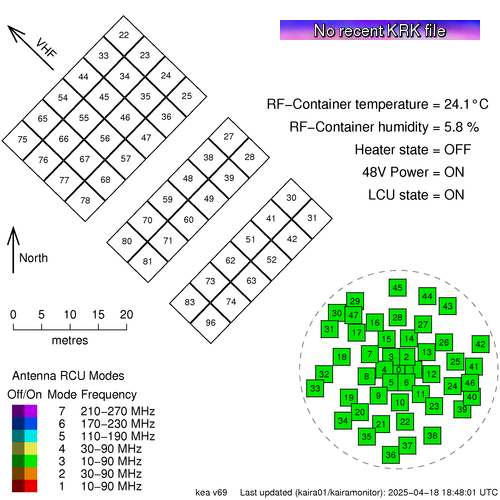
This is available from the Status page, which can be found in the title bar of this web log.
The map shows the array layout of the antennas. The High-Band Antenna (HBA) tiles are in the top left and the Low-Band Antenna (LBA) aerials are in the lower right. The layout is to scale, which is shown, and the direction to the VHF transmitter at Tromsø, is also indicated.
The antennas are numbered and they are also colour coded to show the Receiver Unit (RCU) mode. KAIRA has 96 RCUs and the RCU mode indicates which combination of antenna plus band-pass filter is used for the processing. Sometimes the entire array is configured to a single RCU mode and at other times it is mixed with several different modes for different antennas.
If an antenna is enabled, then the colour is bright, but if it is switched off, then it is dulled down.
In the case of a plain grey antenna icon, this means the antenna is shut down, either for maintenance, or as a result of damage.
Sometimes an antenna might be shaded with two colours like a two-tone maritime-Z-pennant. This is because each antenna has two polarisations, and there will be occasions when the RCU number/status for each polarisation is not the same.
In the bottom left, there is the legend and in the top right is the status label and the current RF-container parameters.
The image at the start of this post is "live". If you update the page, you might see ti change, depending on what KAIRA is doing. But to give an indication of what the status map might look like, here are some other static examples:
This shows the actual current status:
This is available from the Status page, which can be found in the title bar of this web log.
The map shows the array layout of the antennas. The High-Band Antenna (HBA) tiles are in the top left and the Low-Band Antenna (LBA) aerials are in the lower right. The layout is to scale, which is shown, and the direction to the VHF transmitter at Tromsø, is also indicated.
The antennas are numbered and they are also colour coded to show the Receiver Unit (RCU) mode. KAIRA has 96 RCUs and the RCU mode indicates which combination of antenna plus band-pass filter is used for the processing. Sometimes the entire array is configured to a single RCU mode and at other times it is mixed with several different modes for different antennas.
If an antenna is enabled, then the colour is bright, but if it is switched off, then it is dulled down.
In the case of a plain grey antenna icon, this means the antenna is shut down, either for maintenance, or as a result of damage.
Sometimes an antenna might be shaded with two colours like a two-tone maritime-Z-pennant. This is because each antenna has two polarisations, and there will be occasions when the RCU number/status for each polarisation is not the same.
In the bottom left, there is the legend and in the top right is the status label and the current RF-container parameters.
The image at the start of this post is "live". If you update the page, you might see ti change, depending on what KAIRA is doing. But to give an indication of what the status map might look like, here are some other static examples:
 |
| A "357"-mode solar observation. The grey antennas are those knocked out by the March 2014 blizzard. |
 |
| A mode-3 riometry observation. Storm-damaged antennas are also present in this particular example. |
Friday, 4 April 2014
The KAIRA snowscape
It's Friday again and, after a dearth of Friday photographs, we've an absolute treat for you today.
Back in November of 2013, we ran an extended campaign at KAIRA with the University of Southampton, observing pulsars, incoherent scatter radar and various riometry experiments. On one morning, we actually had some clear weather, giving us a chance to take some photographs. And today we feature one of these.
The photograph was taken on 3rd November 2013, and shows the Low-Band Antenna (LBA) array in the central foreground with the HBA behind it and a bit to the right. It is also possible to see the site containers too. The mountains in the background are (from left to right) Pikku Malla, Iso Malla and Sallorássa. The first two are in Finland and the latter is in Norway.
You can click on the above image to see a somewhat larger version. However, for those who really want high-resolution, we have a 3200x1000-pixel version (4 MB) at the KAIRA press-and-media page. Or, if that is not enough, we also have a huge 9600x3000-pixel version (30 MB... Warning: this image may take a while to download). Oh, and a big thank-you to Poppy Martin (U. Soton) for lending her amazing camera to me in order to make the image.
Have a nice weekend, everyone!
Back in November of 2013, we ran an extended campaign at KAIRA with the University of Southampton, observing pulsars, incoherent scatter radar and various riometry experiments. On one morning, we actually had some clear weather, giving us a chance to take some photographs. And today we feature one of these.
 |
| KAIRA 2013-11-03 (Photo: D. McKay-Bukowski) |
The photograph was taken on 3rd November 2013, and shows the Low-Band Antenna (LBA) array in the central foreground with the HBA behind it and a bit to the right. It is also possible to see the site containers too. The mountains in the background are (from left to right) Pikku Malla, Iso Malla and Sallorássa. The first two are in Finland and the latter is in Norway.
You can click on the above image to see a somewhat larger version. However, for those who really want high-resolution, we have a 3200x1000-pixel version (4 MB) at the KAIRA press-and-media page. Or, if that is not enough, we also have a huge 9600x3000-pixel version (30 MB... Warning: this image may take a while to download). Oh, and a big thank-you to Poppy Martin (U. Soton) for lending her amazing camera to me in order to make the image.
Have a nice weekend, everyone!
Saturday, 29 March 2014
The remains
Following the great Kilpisjärvi Storm of 2014, the telescope rescue crew scoured the surrounding landscape trying to find and recover debris. Part of this was recovering as much scattered electronics as possible... some of which may be able to be cleaned up and re-used as spares.
This sad crate of fragments are some of the parts salvaged during that operation. (Click on the photograph to enlarge.)
This sad crate of fragments are some of the parts salvaged during that operation. (Click on the photograph to enlarge.)
 |
| Salvaged parts from the destroyed LOFAR HBA tile at KAIRA. (Photo: L. Roininen) |
Monday, 17 March 2014
Mapping the RCU number to the LBA/HBA number
Each polarisation from each antenna is processed by a separate channel. The electronics on this channel is called a Receiver Unit (RCU). KAIRA has 96 RCUs (numbered 0..95).
When looking at the signals coming into the system, they are labelled by their RCU number in the first instant. One needs to map this to the antennas to work out which antenna/polarisation is being shown.
The polarisation mapping is straight forward... even numbers for X-polarisation and odd numbers of Y-polarisation. However the match between the RCU numbers and the antenna numbers is a bit more confusing. Yes, there is a logic, but it is not obvious. Sometimes it is simply easier to look it up!
So, here is the mapping of RCU to antenna number for KAIRA (the scheme is different for other LOFAR stations).

For where those antennas are on the actual site, refer to the array layout map.
When looking at the signals coming into the system, they are labelled by their RCU number in the first instant. One needs to map this to the antennas to work out which antenna/polarisation is being shown.
The polarisation mapping is straight forward... even numbers for X-polarisation and odd numbers of Y-polarisation. However the match between the RCU numbers and the antenna numbers is a bit more confusing. Yes, there is a logic, but it is not obvious. Sometimes it is simply easier to look it up!
So, here is the mapping of RCU to antenna number for KAIRA (the scheme is different for other LOFAR stations).
For where those antennas are on the actual site, refer to the array layout map.
Sunday, 16 March 2014
Map of the 2014 KAIRA storm damage
Today, we've plotted where there has been damage to KAIRA. The map is a bit scary, but actually as we have seen from yesterday things are not so bad and we've come out of it fairly well.
 As can be seen, we have lost two antennas completely. These are tile #H75 and aerial #L34.
We've had two aerials (#L05 and #L21) seriously damaged. These will need to be replaced.
There are three aerials (#L22, #L35 and #L36) which have been damaged but have been repaired to the point where they are operating normally again. However additional work will be required in the summer when the snow has melted and we can access them properly.
There are many aerials with minor damage. The aerials are still operational, but will require some attention in the summer to ensure they remain robust for the following winter. The problem has been buffeting to the aerial wires causing cracks in the PVC moulding and coatings. These can be patched, but it does require warmer weather.
We've had two aerials (#L05 and #L21) seriously damaged. These will need to be replaced.
There are three aerials (#L22, #L35 and #L36) which have been damaged but have been repaired to the point where they are operating normally again. However additional work will be required in the summer when the snow has melted and we can access them properly.
There are many aerials with minor damage. The aerials are still operational, but will require some attention in the summer to ensure they remain robust for the following winter. The problem has been buffeting to the aerial wires causing cracks in the PVC moulding and coatings. These can be patched, but it does require warmer weather.
Saturday, 15 March 2014
System status
Following the storm and the repair work, we carried out remote system checks for the bandpasses for all antennas. Here are the results, starting with the High-Band Antenna (HBA) array:

As seen, RCUs 80 and 81 (= tile #H75) remain dead. These are the two channels from this destroyed tile.
Here is the Low-Band Antenna (LBA) array results:

Here you can see RCUs 68 and 69 (= aerial #34) remain dead. This aerial was destroyed and we have not even found the remains of it! Following repairs, there remain two other damaged signal channels. These are RCU 11 (= aerial #L05, Y-polarisation) and RCU 42 (= aerial #L21, X-polarisation). These two aerials have suffered broken wires and are thus impared in this polarisation. Temporary repairs have been effected, but more work remains to be done.
However, in total, we only have lost 6 out of 192 signal channels. Throughout the storm and the repair work, KAIRA has continued to observe our riometry and interferometry programmes. That's pretty good.
As seen, RCUs 80 and 81 (= tile #H75) remain dead. These are the two channels from this destroyed tile.
Here is the Low-Band Antenna (LBA) array results:
Here you can see RCUs 68 and 69 (= aerial #34) remain dead. This aerial was destroyed and we have not even found the remains of it! Following repairs, there remain two other damaged signal channels. These are RCU 11 (= aerial #L05, Y-polarisation) and RCU 42 (= aerial #L21, X-polarisation). These two aerials have suffered broken wires and are thus impared in this polarisation. Temporary repairs have been effected, but more work remains to be done.
However, in total, we only have lost 6 out of 192 signal channels. Throughout the storm and the repair work, KAIRA has continued to observe our riometry and interferometry programmes. That's pretty good.
Monday, 10 March 2014
HBA tile #75 flat-lining
Following the high winds of 08-Mar-2013, we carried out a series of remote system tests to verify that KAIRA is still okay and functioning correctly. The best way to do this is to examine the spectrum of every antenna for each polarisation. These are processed by the Receiver Units (RCUs) and there is one for each antenna/polarisation.
The first test we did was for the High-Band Array (HBA). The following is the collected set of spectra for the entire HBA. We expect a broad "Saana-shape" spectrum with occasional vertical spikes of radio-frequency interference (RFI).

As can be seen, there are a couple of weak channels which show non-typical spectra. The RCUs are 80 and 81, which correspond to tile #75 X-polarisation and Y-polarisation. This indicates that there is a problem with the entire tile, and further investigation is needed. Here is the location of the tile in the array:

Given that this is the leading edge against the northwest gales that we have had makes us very nervous.
An expedition to the site will be required.
The first test we did was for the High-Band Array (HBA). The following is the collected set of spectra for the entire HBA. We expect a broad "Saana-shape" spectrum with occasional vertical spikes of radio-frequency interference (RFI).
As can be seen, there are a couple of weak channels which show non-typical spectra. The RCUs are 80 and 81, which correspond to tile #75 X-polarisation and Y-polarisation. This indicates that there is a problem with the entire tile, and further investigation is needed. Here is the location of the tile in the array:
Given that this is the leading edge against the northwest gales that we have had makes us very nervous.
An expedition to the site will be required.
Tuesday, 18 February 2014
Snowverhang
Depending on the prevailing wind, snow and temperature conditions, it is possible to get some interesting effects with the ice along the KAIRA HBA tile edges. Today's photograph shows such an effect.
Although the effect can be seen in the foreground, it was most pronounced further into the snow corridor. (Click on the image for an enlargement.). At the furthest point, the snow was 90 cm overhanging the edge of the HBA tiles.
Note also the way the snow post at the front corner is bending under the snow loading. This is not much, but it does show a general trend of the ice to move across the surface of the HBA array.
 |
| Snowverhang on the KAIRA HBA. (Photo: D. McKay-Bukowski) |
Although the effect can be seen in the foreground, it was most pronounced further into the snow corridor. (Click on the image for an enlargement.). At the furthest point, the snow was 90 cm overhanging the edge of the HBA tiles.
Note also the way the snow post at the front corner is bending under the snow loading. This is not much, but it does show a general trend of the ice to move across the surface of the HBA array.
Tuesday, 31 December 2013
New Year's Eve
Well, that's about it for 2013. It has been a hectic, frantic year with lots going on and all sorts of new discoveries and adventures. To all our dedicated readers, thank you for making 2013 our most successful and for all your positive and encouraging comments.
Today at the institute, we had a little celebration for the 100th anniversary of geophysical measurements (more on that tomorrow).
But tonight's "photograph" is a close-up of the inside of an HBA tile, shot at midnight in the depths of a polar night, with no moon, overcast skies and a complete power failure. The temperature outside is -15 (although those tiles keep it at a toasty -10 C inside them).
:-)
Thanks for 2013!
Best wishes for the new year!!
Today at the institute, we had a little celebration for the 100th anniversary of geophysical measurements (more on that tomorrow).
But tonight's "photograph" is a close-up of the inside of an HBA tile, shot at midnight in the depths of a polar night, with no moon, overcast skies and a complete power failure. The temperature outside is -15 (although those tiles keep it at a toasty -10 C inside them).
 |
| This photograph is intentionally black. (Okay... so we made this one up.) |
:-)
Thanks for 2013!
Best wishes for the new year!!
Tuesday, 24 December 2013
Snowscape at KAIRA
Today's photograph is of the snow and ice at the KAIRA High-Band Antenna array.
 |
| Snow and ice. (Photo: D. McKay-Bukowski) |
Thursday, 5 December 2013
KAIRA for Stellarium
The desktop planetarium "stellarium" is a beautiful way to view the sky from any location and for any time. It also has the added feature of being able to add your own landscapes, thus giving correct horizon views.
Quite some time ago we did this for the KAIRA High-Band Antenna (HBA) array. The result is an Autumnal view of the KAIRA site, from the mid-point of the HBA array.
You can download the KAIRA HBA landscape (link) for your own version of Stellarium. We plan to create an LBA version sometime in the future.
Ref: http://www.stellarium.org/
Quite some time ago we did this for the KAIRA High-Band Antenna (HBA) array. The result is an Autumnal view of the KAIRA site, from the mid-point of the HBA array.
 |
| The view from KAIRA... completely in software! (Image: D. McKay-Bukowski) |
You can download the KAIRA HBA landscape (link) for your own version of Stellarium. We plan to create an LBA version sometime in the future.
Ref: http://www.stellarium.org/
Subscribe to:
Posts (Atom)