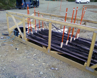
When we designed the LBA array, the original plan was to locate it on the tundra field to the northeast of the HBA array. As we have reported before, this proved to be impossible, due to problems with the soil, snow and prevailing conditions. These things happen in science, but the important thing is that the project can adapt to setbacks and adjust accordingly so that alternatives and workarounds can be found. In the case of the KAIRA LBA array, we have instead deployed the aerials in the solid area to the southeast of the HBA array. In terms of ground stability, this area is perfect. However, it does present a challenge in that extra length is required on the connecting cables.
To overcome this, we are making use of the existing cable set that we have. Firstly, we carefully planned the system of ducts and nodes, and then determined what cable lengths could be expected.
 |
| Diagram of the LBA field, with cable runs marked. The shading indicates the length of the cable required to a given location. The lighter the shading, the longer the cable length. The lengths are all calculated by the routing/planning software that we have written, thus allowing us to optimise the use of the existing cables, and thus minimise waste and keep down cost. |
Then, the installation order and placement was determined. We compared this to our cable inventory, of the parts that we actually have and worked out that we could complete the array with the following lengths:
2 × 80m pairs
20 × 115m pairs
24 × 120m pairs
2 × 130m pairs
In fact, the 120 and 130m lengths were made by joining cables together. The 130m lengths were made by joining existing 80m and 50m cables from our inventory together. The 120m cables were made by joining existing 80m cables with 40m cables. There is no standard 40m cable length, so the ones we used were made by cutting a 80m cable in half.
As you can probably tell, we have lots of 80m cable lengths in our inventory.
The reason why the cables come in set lengths is for ease and cheapness of manufacture. The tolerances on the cable lengths that we use are quite strict, so we need to control this process quite carefully. Additionally, it is important that the propagation delay (how long it takes the signal to travel down the cable) is known very accurately... ideally to a fraction of a nanosecond. You make remember from our "
how it works" series, that the pointing direction of the instrument is controlled by controlling the signal path delays. So, to be able to do this well, you need to know the existing delays in all the cables before adding any more.
This work has now been done and we are putting together the calibration tables now. I will post some photographs for the cable work, along with some others from the LBA build tomorrow.


