Sunday 31 July 2011

Keeping the owls company

Let's face it... all the cool receiver stations have owls. And, not to be outdone by the owls at the LOFAR site at Chilbolton, UK, KAIRA is proud to announce that we have a family of owls too.

Three of us were working out at the site at around midnight when we spotted a grey shape swooping through the array. At first we saw only the one, but then it became apparent that there were three owls too... and one seemed a little unsteady; an owlet perhaps?

We watched fascinated for a while as then moved about before flying on. It was quite dark (we're in that deep twilight phase at midnight now) and they were not too close. The photograph was the best I could manage in time (by the time I'd zoomed it, it had flown to a new position).

The owl is perched right on the north corner of the tile.

At this stage we're not completely certain what type of owl it is. Hopefully our wildlife expert will be able to solve the mystery. No doubt there will be more on this story when we tell him about it in the morning. Stay tuned!

The quiet moments

For the most part, the KAIRA team have worked extremely hard. We have accomplished the major tasks that we set out to do and, despite some pretty serious unforeseen problems, we've managed to get through everything okay, with only minor delays to the schedule.

However, despite all the hard work, there are also a few breaks and some moments when the site planning team desperately need some space to figure out the next stage of the build. This gives everyone a few brief moments to take it easy and relax.

Although we've mentioned a few examples, such as wildlife-spotting, there are a few other light-hearted moments we managed to capture on camera.


Pertti goes fishing from the cable mausoleum with one of the draw lines...


... but the best he could manage was a coffee cup. Hey, couldn't you haul out some more rocks?


Back from cutting tundra, Mikko and Santtu demonstrate the ancient and revered Lappish
tradition of making birch whistles. (Despite first appearances, they are not eating them!)

Siilasjärvi

Although KAIRA is the Kilpisjärvi Atmospheric Imaging Receiver Array, the fact is that it is closer to Siilasjärvi, than Kilpisjärvi. Siilasjärvi is a small lake to the north, but it rarely shows up on maps, and there is certainly no settlement there. However, that doesn't detract from the natural beauty of this lake. So, this morning, we have a photograph taken from the southern end of the lake looking northwards.

Click on the image for the full-size version.

KAIRA is on the right-hand shore, but is probably just off the field of view. In any case, it is obscured by trees from this vantage point. However, this second photograph (taken from nearby Pikku Malla) shows the entire of Siilasjärvi.


The three sites right in the middle of the photograph along the road are, from left to right, KAIRA, the customs station and, on the opposite side of the road, the customs barracks.

These photographs were taken on the evening of 28th July 2011 after work. It had been a fine day and the evening was cool, but sunny. The air was clear and the wind calm. So some of the team decided to head up to Pikke Malla from whence the photographs were taken.

The team (from left to right): Arttu Jutila, Juha Vierinen,
Pertti Nissinen, Stuart Keenan and Ilkka Virtanen. KAIRA
can be seen in the distance, just to the right of Ilkka.


Photos: D. McKay-Bukowski

Saturday 30 July 2011

The tooling returns

Some of the tools that were used to install the LOFAR HBA tiles at the KAIRA site were provided by ASTRON (the Netherlands Foundation for Radio Astronomy). These tools move from site to site as the stations are rolled out across Europe. Now that the installation work is complete, the equipment used in the operation needs to returned.

The unfolding station, generators, tool boxes and spare parts are loaded onto the return lorry.

Rocks, rocks and more rocks

As we reported a couple of days ago, there had been some problems with two collapsed cable ducts. This had prompted us to completely excavate the cable trench in that sector and replace the ducting.

Well, although we managed to get those rocks, the ducts were still moderately close to the surface. Thus the decision was made to continue digging down to better establish to trench and put the ducts at a safer depth.

Removing the last few 'pebbles' from the trench bed was non-trivial and it took a large portion of the day to get things to an acceptable state.

Of course, other LOFAR stations would not have had this problem (although the RAF-base foundations at Chilbolton may have come close). They tend to be on flat ground, perfectly drained, with a decent layer of top-soil, manicured lawns... okay, okay, I'm exaggerating now, but you get the idea.

Put a massive receive array in a rugged location and you can only expect rugged ground conditions too.

Anyway, here are some of the photographs that we took during a day of very hard work.


Rauno Oikarainen, Marko Kauranen and Pertti Nissinen pause
for breath before lifting out one of the smaller specimens.


Markku Postila and Rauno Oikarainen drive in some levers to try to dislodge the next one.


Some were a bit big and required some mechanical assistance for their removal.


Stuart Keenan and Marko Kauranen fit some lifting straps around an
even larger example. (Watch out for any lurking lemmings, Stuart!)


But even the Land Cruiser couldn't manage this one.


A borrowed tractor from the University of Helsinki was used to finish the job.


With all the rocks (finally!) cleared from the trench we put down a layer of sand to even things out and then recommenced the laying of the cable ducts ready to run the cables. There will be some more photographs of that coming soon. (Hopefully by the end of the weekend, the web log will have caught up with its own progress reports!)

Friday 29 July 2011

HBA cabling progress — 29-Jul-2011

Today, we continued work on the HBA cables. With not quite as many people on site today, some additional work to be done and some planning and checking, we did not get quite as many done. However, we have now completed the first block of cables and are ready to go with the next block for Monday morning. As far as our revised schedule is concerned, this is on track.


The completed antennas are shaded in orange and white. This is because these are the colours used on the labels of the X- and Y-polarisations (respectively).

During the weekend, we shall be working on the planning for the next stages of the build. Apart from organising the electronics for the RF container, there is the initial planning work to be done for the LBA. It is almost a year ago that we carried out the first site survey and that was planned last August. So, it is time to get working on the planning for the LBA build for next year.

Oh... and the weekend will be a great chance to catch up on all the unpublished photographs we've been taking for the web log!

Some views from Pikku Malla

We have some great photographs from some of our trainees to end the week this week. The first was taken on 23rd July 2011 by Marko Kauranen. It was taken on 23rd July 2011, the day after the last tile was installed on the HBA.


The second photograph was taken on the evening of 24th July 2011. It was taken by Arttu Jutila, who has contributed some great photographs from this viewpoint before.


Between the times of the two photographs, the RF-container has been installed, and it can clearly be seen in the second image, to the left-hand side of the array.

Both photographs were taken from the nature reserve trail that leads from the shore of Kilpisjärvi, over the bridge at the south-end of Siilasjärvi and then up to Pikku Malla. Thanks go to Marko and Arttu for contributing them to this web log.

Have a great weekend!

Post drivers

There are a lot of fence posts around the site. It is a big area and the reindeer fence goes around all of it. After a couple of false-starts, we have finally found a method and equipment (and volunteers!) to get the job done of driving these posts hard into the ground. So throughout the site the baleful clanging of the post driver can be heard.

Arttu Jutila and Santtu Rantakokko pound another reindeer fence post into the ground.

Thursday 28 July 2011

HBA cabling progress — 28-Jul-2011

Today, we continued our work on laying cables for the KAIRA HBA. The progress so far is shown below.


Each antenna that has had cables run out to it is shaded. The orange shading indicates there is an X-polarisation cable installed. The white shading indicates that there is the Y-polarisation cable in place. As can be seen (click on the chart for an enlargement if required), antenna H41 only managed to get its X-polarisation cable today.

The reason for the orange/white shading is that these are the cable label-colours used. Each cable is marked with a colour-coded, bar-coded label and the scheme we have used here is to match that. More on this later!

As can be seen, we made some good progress today.

Hard rock

No, despite KAIRA being a Finnish project, this is not an article about the 2006 Eurovision Song Contest. Instead, the title of this post is a reference to the issues we'd encountered with the cable ducts being crushed. Part of the problem seemed to be that the ground itself is rocky, uneven and difficult to work with.

Having cleared out the trench and removed the crushed pipes, we then decided to try to level the trench base down and get it flatter and deeper.

Despite some solid digging, we were having trouble due to some moderate sized rocks in the ground. These took a lot of work to prise them loose to shift them away.

Stuart and Marko roll over a rock. They make it look so easy.

Actually, that one was a bit heavy, so we brought in the Land Cruiser to drag it out.

Stuart and Arttu stand clear as we haul out a larger specimen.
A bit further back are some earlier hand-extracted prizes!

Ducting problems

With the cables checked and the mausoleum complete, it was time to try running through the first 115m cable pair. This would go from the RF-container, through all the ducts and out to antenna tile location HXX (far western corner).

Ilkka Virtanen checks the ducting prior to the first cable-run attempt.

We got the cable through the RF-container ducts, and then the first stretch from the mausoleum to the 'corner' before heading up to the array. However, the final stretch to the array was somehow blocked. We worked at it for a bit before recovering a loose piece of geotextile that was blocking the tube. However, the cable-pair still refused to go through.

The draw string was working, and some checks with rope were also working. However using the 'lemming' didn't. The 'lemming' is our nickname for an improvised test canister. It is attached to the draw-string loops and can be used to check that a cable duct is clear. The name is from the fact that a lemming is what would be best able to check on the duct situation. And this is the closest we can approximate to a lemming!


Taping the 'lemming' to the draw-string for another reconnaissance mission!

Well, it turned out that we had a serious blockage. We suspected that there might be a problem with one of the frameset anchors having pierced the duct pipe. However, a test excavation indicated that this was not the case. What we did find, however, was some seriously crimped pipework! As a result, we checked all the ducts and realised that there was just one stretch where two of the four pipes were blocked. So we excavated the entire area.


The team digs out the four-pipe run by the northern array corner.

Sure enough, this is what we found.

Crushed cable ducts.

These crimped pipes are probably due to extreme ground pressure during the movement of vehicles overhead.

Well, we have no choice by the re-work the trench and put down new pipe.

Wednesday 27 July 2011

HBA cabling progress — 27-Jul-2011

In the same way that we reported on the progress of the installation of the tile antennas, we've also been asked to do the same for the installation of the HBA cables. As has been described, there are two cables from each antenna to the RF-container, where the signal processing electronics is located.

Today, we only installed one cable pair, for the furthest antenna — HXX.


It took us a long time to get the cables for this antenna installed. Hopefully, the pace will pick up a bit as we clear out the problems and become more experienced.

Patch panels

Inside the RF-container there is a second lining, with a great RF-shielded door. This is what is known as a Faraday Shield. This inner lining (when closed) will prevent spurious radio signals from escaping. These could then be detected by the antennas themselves, thus thwarting the experiment being carried out by the completed instrument.

However, the signals from the antennas need to get inside, of course, so to do this a carefully shielded and grounded 'patch panel' is used.

The photograph shows the patch panels in the KAIRA RF-container. They are the white panels on the wall. The top one is for the LBA and the lower one is for the HBA. Each panel has 200 holes. These are for the maximum of 192 signal cables from each array, plus 8 spares.

The pipes coming out of the floor are the ducts to the outside. Although empty at the moment, these will be filled as the project is wired-up. The first ducts to be used will be the two closest to the patch panels.

Cable mausoleum

The cable mausoleum is used to store excess lengths of the cable from the array. Normally this cable is buried (in what is called a cable 'grave'). However, for KAIRA this needs to be above ground (hence the corresponding term 'mausoleum').

As will be seen over the next few days, this containment space will end up holding up the surplus signal cable. It is like a table, upon which the excess length will be zig-zagged back and forth. And, at either end, there are ducts going down into some of the few places where cables go underground.

Rauno Oikarainen,Pertti Nissinen and Arttu Jutila assemble the cable mausoleum.


Another view of the mausoleum frame in front of the RF-
container, clearly showing the input and output ducting.

HBA cable lengths

Because it is important to control the cable lengths for the phased array, each cable is made to a specific length. And to ease the manufacturing process, these lengths are standardised to a small number of set lengths. These are divided across the array as follows:


For the KAIRA HBA, there are two set lengths: 85 metres (blue) and 115 metres (amber). The grey/white tiles in the diagram are the positions of a full international HBA. These are not being implemented now, but are reserved as possible future locations.

The total number of cables is 96. That is because there are two cables per tile. The numbers on each tile are their ID numbers (e.g. H74); beneath is the actual distance required (e.g. 109.5m).

Because of the positions of the HBA tiles and the set length cables, there can be several tens of metres of excess cable which needs to be carefully zigzagged back and forth before the remainder of the cable goes into the RF-container. These will be stored above ground.

As on a normal LOFAR international station, the buried cables are referred to as being in a 'cable grave', the KAIRA above-ground surplus storage unit is referred to as the 'cable mausoleum'.

Tuesday 26 July 2011

Electronics and cables

As part of the recent delivery, we received a lot of electronics, cables and ancillary equipment. We spent a bit of time moving things around and getting organised for the week.

Santtu Rantakokko and Marko Kauranen shift the sub-rack
assemblies from the Land Cruiser into the auxiliary container.


In addition to the electronics, there are a lot of cables. In fact a total of 576 signal cables were delivered, with a total length of 27268 metres!

Of that distance, 96 cables (nearly 10 km in total) will be deployed as soon as possible onto the HBA field. The remaining cables are either for the RF-container or for the LBA installation for next year. Although the quality of the supplied cables, we checked every single one for the signal attenuation and group delay to ensure that it is correct before taking it over to the RF-container for installation.

Juha Vierinen uses the network analyser to check one of the cables.
This work is being done in the so-called Lehtinen Barracks.


We spent a couple of evenings and one work day sorting out the measurement technique and then checking all the HBA field cables. The work went very quickly and the team's progress was outstanding.

Once the testing was completed the cables were taken out to the RF-container where they are stacked ready for feeding through the cable ducts to connect to the antennas.

Santtu Rantakokko and Juha Vierinen unload cables from the Land Cruiser to the RF-container.


Stacks of 115m cables in the RF-container, ready to go!

LBA grids

Underneath each Low Band Array (LBA) antenna, there is a metal grid. This mesh is 3m × 3m and is made of reinforcing steel. Along with the RF and auxiliary containers, we also received delivery of a load of 100 of these steel grids.

Unloading them proved to be non-trivial.

The grids were in two stacks of 50 pieces, each probably over a tonne. By itself, this is not so much of a problem. However they are abrasive, flexible, awkward to handle and... with jagged edges.

During the first lift one of our lifting straps broke, causing the load to crash to the ground. Damage was minimal, and no-one was hurt, but it gave us a bit of a scare.


With new lifting rigs we made the attempt again. In the next photograph, Marko Kauranen and Santtu Rantakokko secure a set of lifting chains.


The next attempts managed to get the grids into place.


Finally... a stack of LBA grids. Ready for next year.


Photos: D.McKay-Bukowski

Auxiliary container

The next item on the delivery lorry for 25th July 2011, was the auxiliary container.


This container provides additional storage. It also came with various pieces of equipment inside that would be needed for the installation.


Unlike the RF-container, unloading and placing this was pretty straight-forward. However, the following load proved to be difficult and dangerous. Stay tuned!

Photos: D. McKay-Bukowski

RF-container

Yesterday (25th July 2011) we received a pretty big delivery. A road train arrived with two shipping containers and a couple of stacks of steel grids.


The first container (brown) is the auxiliary container. This will be used for additional storage capacity on the site (shipping containers are cheaper and easier to reposition than permanent structures). However, this was not the first to be unloaded and put in place.

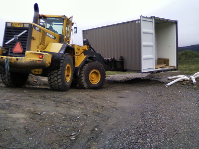
The second container (the grey one) is the RF-container. For those who have been following this web log (we admire your endurance!), you will know that this shipping container is shielded against electrical noise and will house the bulk of the digital signal processing electronics.

To get it from the delivery lorry to the northern corner of the array, we used the trusty 15-tonne digger. After a delicate moment trying to negotiate the forks into the container lifting slots we eventually managed it and drove it down to the array end through the rain.


The final stretch was quite difficult. Apart from the turns and the slope, there was an open trench from the electrical power cabling. Although we had hoped to leave this open to make the post-installation work easier, we realised that this was not going to be possible, so the team rapidly filled in the trench while the digger waited with the 5-tonne container held precariously aloft.


With the area ready, we hauled open the container doors (so we could feed in the cable ducting). Then it was time to move and lower the container onto the concrete foundation blocks.


Getting this into position was not easy and we needed to to-and-fro multiple times to get the alignment just right. Credit is due to the digger driver who did an expert job of getting this just right.


Once in place, the then attempted to extricate the digger forks. However, by this time, the angle of the digger and the weight shift of the container had jammed them in hard and any attempt to pull free was bringing the container along with it!

After numerous frustrated attempts, Rauno Oikarainen hit upon the idea of knocking them out from the opposite side with lengths of timber and a sledge hammer. So, we disconnected the digger from the forks, backed it off, and then proceeded to successfully accomplish the task.

Phew!

That was a difficult and time consuming process, but the container was now in place. More unloading to follow... in the next article!

Monday 25 July 2011

Cable tunnels

Between the array itself — which handles cable routing with timber 'V' and 'U' trays — and the RF-container, there is some complicated ducting work to be done. This is to protect the cables but also to take up any surplus length before they are routed into the cramped RF-container.

Because we need to protect the cables from direct contact with the soil, which is subject to frost-heaving and other freezing effects, they must be sent through free-air ducts. These are lengths of flexible plastic pipe in which the cables can sit freely and move if the pipes themselves are shifted by ground disturbances.

Placing these pipes is a tricky business. They seem to have a mind of their own and will not stay put as one would like. Instead, we need to tie them up, batten them down, but otherwise tolerate their wayward behaviour.


Once the RF-container and cable mausoleum are in place, we can them tie them into place and bury the remainder to secure everything.

In the photograph at the lower right, Marko Kauranen considers how on earth he's going to get the next two ducts to sit with the others already in the final access trench that will link the cable mausoleum to the RF-container. (Yes, he did manage it!)

Photos: D. McKay-Bukowski

Installing the cable trays — Part 2

At the end of each row, bundles of 12 signal cables (2 polarisations, for each of 6 antennas) will emerge and enter the main trunking route that runs along the north-eastern edge of the array.

Along here we have a larger type of cable tray, comprising three planks of timber. These so-called 'U' trays hold twice the number of cables as the 'V' trays already discussed.


Pertti Nissinen (left) and Rauno Oikarainen assemble a 'U'-tray.


Sets of 'U'-trays near the start of the underground
ducting. There is a gradual drop along the entire
length of these main cable trays for water drainage.

The cables from each row's 'V' tray feed into these 'U' trays and continue up the north corner of the array where they enter underground ducts to go the cable mausoleum and RF-container. The installation of all cable trays has now been completed. This week, we're putting in the container and mausoleum, prior to commencing the actual cable work. It is going to be a busy week!

Photos: D. McKay-Bukowksi

Installing the cable trays — Part 1

The KAIRA array is a semi-sparse array with six columns and eight rows — forty-eight antennas in total. Each antenna has two signal cables, which means ninety-six cables to be taken back to the RF-container, where the bulk of the signal-processing electronics is located. As we have recently seen, this is being done using timber cable trays, mounted underneath each tile antenna. These are organised so that the cables first run along the 'V' trays that run under the six antennas in each row.

These are pre-constructed in the open and then are inserted into the framesets which support them. In the photograph at the top left, Mikko Tilja (left) and Johannes Turunen insert a 'V' tray onto the support structure.

Once in place, these trays will hold between two and twelve cables (depending on where along the row they are), and bring them to the north eastern edge of the array, where they will link with the main cable trunking. The photograph to the right is the view along the cable tray. The illuminated spot is where the tray passes under the small gap between the tile antennas.

Photos: D. McKay-Bukowski